

Infineon and EVs: Power Semiconductors for Charging & More
Learn how Infineon’s power electronics and automotive semiconductors enable EV drivetrains, fast charging, and efficient industrial motors—plus key terms to know.
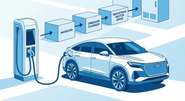
Why Infineon Matters in EVs, Charging, and Industry
If you care about EV range, charging speed, and long-term reliability, you’re ultimately talking about how efficiently electrical energy is converted and controlled. That job is done by semiconductors—especially power semiconductors that act like ultra-fast, high-current switches.
Infineon matters because it’s one of the major suppliers of these “gatekeepers” of energy flow. When switching losses are lower and heat is easier to manage, more of the battery’s energy reaches the wheels, less is wasted during charging, and components can be smaller—or last longer.
What this article will cover (in plain terms)
This is a practical, non-technical overview of the key building blocks inside:
- EVs (how battery power becomes smooth motion)
- Charging infrastructure (how the grid delivers energy quickly and safely)
- Industrial systems (how factories cut electricity use in motors and power supplies)
Along the way, we’ll connect the dots: higher efficiency can translate into more range, shorter charge sessions, and less thermal stress—a major driver of reliability.
Power electronics vs. signal/logic electronics
It helps to separate two categories that often get lumped together:
- Power electronics handle energy: high voltage, high current, heat, and efficiency (inverters, chargers, motor drives).
- Signal/logic electronics handle information: sensing, communication, control, and computing (microcontrollers, networking, safety controllers).
Both matter, but power electronics are the reason an EV can move, a fast charger can deliver hundreds of kilowatts, and an industrial motor system can save significant energy over its lifetime.
Power Electronics Basics: The Building Blocks
Power electronics is “traffic control” for electricity: it decides how much energy moves, in what direction, and how quickly it can change. Before diving into EV inverters or chargers, a few simple ideas make everything else easier to follow.
Voltage, current, and power (plain language)
- Voltage (V) is the push that drives electricity through a circuit—like water pressure.
- Current (A) is the flow rate—how much electricity is moving.
- Power (W) is how fast energy is being delivered or used: power = voltage × current.
When an EV accelerates or a fast charger ramps up, power electronics manages that power delivery while trying to waste as little as possible as heat.
What “switching” really means
A power switch is a semiconductor device that can turn energy flow on and off extremely fast—thousands to millions of times per second. By switching rapidly (instead of “resisting” the flow like an old-style control knob), systems can control motor speed, charging current, and voltage levels with far higher efficiency.
The main device families you’ll hear about
- MOSFETs: fast switches often used at higher switching frequencies.
- IGBTs: strong performers for high power in many traction and industrial applications.
- Diodes: one-way valves for current; essential in rectification and freewheeling paths.
- Gate drivers: the “translator” that tells a MOSFET or IGBT exactly when—and how hard—to switch.
(Infineon and its peers ship these as discrete components and as high-power modules designed for automotive and industrial environments.)
Where efficiency is lost: conduction, switching, heat
Two primary loss mechanisms are:
- Conduction loss (energy wasted while the switch is on)
- Switching loss (energy wasted during the on/off transitions)
Both become heat. Less loss usually means smaller heatsinks, lighter cooling systems, and more compact hardware—big advantages in EVs and chargers where space, weight, and reliability margins are tight.
EV Traction Inverters: Turning Battery Power Into Motion
An EV battery stores energy as DC (direct current), but most traction motors run on AC (alternating current). The traction inverter is the translator: it takes high-voltage DC from the pack and creates a precisely controlled three‑phase AC waveform that spins the motor.
A simple mental model looks like this:
Battery (DC) → Inverter (DC-to-AC) → Motor (AC torque)
Why the inverter shapes how an EV feels
The inverter isn’t just a “power box”—it strongly influences driving behavior:
- Acceleration and smoothness: Rapid switching controls motor torque in milliseconds. Better control and cleaner switching can reduce vibration, audible whine, and torque ripple.
- Range and efficiency: Every watt lost as heat in the inverter is a watt not reaching the wheels. Lower switching and conduction losses improve real-world efficiency.
- Regenerative braking: The same hardware routes energy back from the motor to the battery. Efficient conversion directly affects how much energy you recover.
Where semiconductor “modules” fit
Many EV inverters are built from multiple layers:
- Power stage: high-power switches (for example, IGBT modules or SiC MOSFET modules) that do the heavy lifting.
- Gate driver and control: driver ICs and controllers that command the switches safely and precisely.
- Sensing and protection: current/voltage sensing, isolation, and fault protection that detect problems early and prevent damage.
The key trade-offs engineers balance
Design choices are a constant negotiation between cost, efficiency, and compactness. Higher efficiency can reduce cooling needs and enable smaller housings, but may require more advanced devices or packaging. Compact designs, in turn, demand excellent thermal performance so the inverter stays reliable under towing, repeated acceleration, or hot weather.
Onboard Chargers and DC/DC: The Hidden Workhorses
When people talk about EV charging, they picture the charge port and the station. Inside the car, two less-visible systems do a lot of the work: the onboard charger (OBC) and the high-voltage to low-voltage DC/DC converter.
What the onboard charger (OBC) actually does
The OBC is the EV’s “AC charging computer.” Most home and workplace charging delivers AC power from the grid, but the battery stores DC power. The OBC converts AC-to-DC and applies the charging profile the battery requires.
A simple way to remember the split:
- AC charging: conversion happens in the car (OBC).
- DC charging: conversion happens in the charger (the station sends DC straight to the battery).
DC/DC: keeping the 12 V system alive
Even with a large high-voltage battery, EVs still rely on a 12 V (or 48 V) system for lights, infotainment, ECUs, pumps, and safety systems. The DC/DC converter steps the traction battery voltage down efficiently and keeps the auxiliary battery charged.
Why high-frequency switching makes chargers smaller
Modern OBCs and DC/DC converters use fast switching semiconductors to reduce the size of magnetic components (inductors/transformers) and filtering. Higher switching frequency can enable:
- smaller, lighter power stages
- faster control response
- potential efficiency gains (when losses and EMI are managed well)
This is where device choices—silicon MOSFETs/IGBTs vs. SiC MOSFETs—directly affect how compact and efficient a charger can be.
Key concerns: power factor, isolation, and safety
An OBC isn’t only about “turning AC into DC.” It must also handle:
- Power Factor Correction (PFC) to draw current cleanly from the grid
- Galvanic isolation (often via a high-frequency transformer) to protect occupants and meet standards
- Protection and sensing for voltage, current, temperature, and isolation monitoring
Charging speed vs. heat: the system trade-off
Higher charging power increases current and switching stress. Semiconductor selection influences efficiency, heat generation, and cooling requirements, which can limit sustained charging power. Lower losses can mean faster charging within the same thermal budget—or simpler, quieter cooling hardware.
DC Fast Charging Hardware: What Semiconductors Enable
DC fast charging looks simple from the outside—plug in, watch the percentage climb—but inside the cabinet it’s a staged power-conversion system. The speed, efficiency, and uptime are largely determined by the power semiconductors and how they’re packaged, cooled, and protected.
What’s inside a fast charger
Most high-power chargers have two main blocks:
- AC/DC front end that takes grid AC and turns it into a stable high-voltage DC “bus,” while meeting grid requirements.
- DC/DC power stage that adjusts that DC bus to the battery’s needs (voltage and current) and coordinates with vehicle protocols.
In both stages, switching devices (IGBTs or SiC MOSFETs), gate drivers, and control ICs determine how compact the charger can be and how cleanly it interacts with the grid.
Efficiency isn’t just a spec sheet number
A 1–2% efficiency difference sounds small, but at 150–350 kW it becomes meaningful. Higher efficiency means:
- less electricity lost as heat (lower energy cost per kWh delivered)
- smaller or slower fans/pumps (less auxiliary power)
- reduced thermal stress on components (often improving service intervals)
Reliability and safety fundamentals
Fast chargers face surges, frequent thermal cycling, dust and humidity, and sometimes salt-air exposure. Semiconductors enable fast protective functions such as fault shutdown, current/voltage monitoring, and isolation boundaries between high-voltage power and low-voltage controls.
Interoperability and safety also depend on dependable sensing and fault handling: insulation monitoring, ground-fault detection, and safe discharge paths help ensure the charger and vehicle can stop power flow quickly when something goes wrong.
Why power modules matter
Integrated power modules (instead of many discrete parts) can simplify layout, reduce stray inductance, and make cooling more predictable. For operators, modular power stages can also make servicing easier: swap a module, validate, and return the charger to operation faster.
Silicon vs SiC: How Material Choice Changes Performance
Choosing between silicon (Si) and silicon carbide (SiC) power devices is one of the biggest levers EV and charger designers have. It affects efficiency, thermal behavior, component size, and sometimes even the shape of a vehicle’s charging curve.
Wide-bandgap, explained without the physics lesson
SiC is a “wide-bandgap” material. In plain terms, it tolerates higher electric fields and higher operating temperatures before it starts leaking current or breaking down. For power electronics, that translates into devices that can block high voltage with lower losses and switch faster—useful in traction inverters and DC fast charging.
Si vs SiC in EVs and charging
Silicon (often as IGBTs or silicon MOSFETs) is mature, widely available, and cost-effective. It performs well, especially when switching speeds don’t need to be extreme.
SiC MOSFETs typically deliver:
- Higher efficiency at high voltage and high power, especially at partial load
- Less heat to remove, which can reduce heatsink and coolant demands
- Potentially smaller systems, because some supporting parts (notably magnetics) can shrink
Those gains can help extend driving range or allow sustained fast charging with less thermal throttling.
Where IGBTs are still common (and why)
IGBT modules remain popular in many 400 V traction inverters, industrial drives, and cost-sensitive platforms. They’re proven, robust, and competitive when the design prioritizes price, established supply chains, and switching frequencies that don’t push silicon too hard.
Why “higher switching frequency” matters
Faster switching (a SiC strength) can unlock smaller magnetics—inductors and transformers in onboard chargers, DC/DC converters, and some charger stages. Smaller magnetics reduce weight and volume and can improve transient response.
One caution: devices don’t guarantee system wins
Efficiency and size benefits depend on the whole design: gate driving, layout inductance, EMI filtering, cooling, control strategy, and operating margins. A well-optimized silicon design can outperform a poorly implemented SiC one—so material choice should follow system goals, not headlines.
Packaging and Thermal Design: Keeping Power Cool and Reliable
Power semiconductors don’t just need the “right chip.” They need the right package—the physical form that carries high current, connects to the rest of the system, and moves heat away fast enough to stay within safe limits.
Why packaging matters (heat out, current in)
When an EV inverter or charger switches hundreds of amps, even small electrical losses become significant heat. If that heat can’t escape, the device runs hotter, efficiency drops, and parts age faster.
Packaging solves two practical problems at once:
- Low-resistance current paths so less power is wasted as heat
- A fast thermal path from the chip to a heatsink or cold plate
This is why EV-grade power designs pay close attention to copper thickness, bonding methods, baseplates, and thermal interface materials.
Modules vs discrete components (plain-English view)
A discrete device is a single power switch mounted on a circuit board—useful for smaller power levels and flexible layouts.
A power module groups multiple switches (and sometimes sensors) into one block designed for high current and controlled heat flow. Think of it as a pre-engineered “power building block” rather than assembling everything from individual bricks.
Thermal basics you’ll hear in datasheets
- Junction temperature (Tj): how hot the silicon (or SiC) actually is inside
- Heatsinks and thermal interface materials: the “heat highway” to the outside world
- Liquid cooling: common in high-power inverters and fast chargers, using a cold plate to remove heat more aggressively
Reliability: surviving real life
EV and industrial environments punish hardware: vibration, humidity, and repeated thermal cycling (hot–cold–hot) can fatigue bonds and solder over time. Strong packaging choices and conservative temperature margins improve lifetime—helping designers push power density without sacrificing durability.
Battery Management and Safety: Sensing, Isolation, Protection
An EV battery pack is only as good as the system supervising it. The Battery Management System (BMS) measures what’s happening inside the pack, keeps cells aligned through balancing, and steps in fast when something looks unsafe.
What the BMS actually does
At a high level, a BMS has three jobs:
- Measurement: reading cell voltages, pack current, and temperatures in real time
- Balancing: equalizing cells so one weak cell doesn’t limit usable range or accelerate aging
- Protection: preventing overcharge, over-discharge, overcurrent, and overtemperature events (by commanding contactors, limiting power, or triggering shutdown)
The sensing that makes everything else possible
BMS decisions depend on accurate sensing:
- Current sensing determines charge/discharge power, enables state-of-charge estimation, and detects short-circuit or unexpected loads
- Voltage sensing (cell-by-cell) spots imbalance early and protects against damaging overcharge/over-discharge
- Temperature sensing supports thermal management and safety limits
Small accuracy errors compound into bad range estimates, uneven aging, or late fault detection—especially under high load or fast charging.
Isolation and high-voltage safety
High-voltage packs must keep control electronics electrically separated from the power domain. Isolation (isolated amplifiers, isolated communication, insulation monitoring) protects passengers and technicians, improves noise immunity, and enables reliable measurement even in the presence of hundreds of volts.
Functional safety, without the jargon
Functional safety is largely about designing systems that detect faults, enter a safe state, and avoid single points of failure. Semiconductor building blocks support this with self-tests, redundant measurement paths, watchdogs, and defined failure reporting.
Diagnostics and fault detection
Modern battery electronics can flag abnormal sensor readings, detect open wires, monitor isolation resistance, and timestamp events for post-fault analysis—turning “something’s wrong” into actionable protection.
Industrial Efficiency: Motor Drives and Factory Energy Savings
Motor drives are one of the biggest “quiet” users of electricity in industry. Anytime a factory needs motion—spinning, pumping, moving, compressing—power electronics sits between the grid and the motor to shape energy into controlled torque and speed.
Where power electronics shows up in factories
A variable-speed drive (VSD) typically rectifies incoming AC power, smooths it on a DC link, then uses an inverter stage (often an IGBT module or SiC MOSFETs, depending on voltage and efficiency goals) to create a controlled AC output for the motor.
You’ll find these drives in pumps, fans, compressors, and conveyors—systems that often run for long hours and dominate a site’s energy bill.
Why variable speed saves energy
Constant-speed operation wastes energy when the process doesn’t need full output. A pump or fan throttled by a valve or damper still consumes near-full power, but a VSD can reduce motor speed instead. For many centrifugal loads (fans/pumps), a small speed reduction can produce a much larger power reduction, translating into real efficiency gains.
Efficiency levers: devices, control, and losses
Modern industrial power devices improve drive performance in practical ways:
- Lower switching and conduction losses with better silicon and wide-bandgap options like SiC MOSFET technology
- Smarter control (more accurate current sensing, faster protection) to run motors closer to their optimal point
- Reduced thermal stress so systems can be smaller or last longer at the same output
Benefits beyond energy
Higher-quality motor control often means quieter operation, smoother starts/stops, less mechanical wear, and better process stability—sometimes as valuable as the energy savings themselves.
Grid and Renewables: Power Conversion Beyond the Car
EVs don’t exist in isolation. Every new charger plugs into a grid that also has to absorb more solar, wind, and battery storage. The same power conversion concepts used inside the car show up in solar inverters, wind converters, stationary storage, and the equipment that feeds charging sites.
Integrating solar, wind, and storage
Renewables are variable by nature: clouds move, wind gusts change, and batteries switch between charging and discharging. Power electronics acts like a translator between these sources and the grid, shaping voltage and current so energy can be delivered smoothly and safely.
Bidirectional power flow (V2H/V2G)
Bidirectional systems can move energy both ways: grid → vehicle (charging) and vehicle → home/grid (supplying). Conceptually, it’s the same hardware doing the switching, but with controls and safety features designed for exporting power. Even if you never use vehicle-to-home or vehicle-to-grid, the bidirectional requirement influences how next-generation inverters and chargers are designed.
Power quality: harmonics and power factor
Conversion can distort the AC waveform. Those distortions are called harmonics, and they can heat equipment or cause interference. Power factor measures how cleanly a device draws power; closer to 1 is better. Modern converters use active control to reduce harmonics and improve power factor, helping the grid handle more chargers and renewables.
Reliability and serviceability matter
Grid equipment is expected to run for years, often outdoors, with predictable maintenance. That pushes designs toward durable packaging, strong protection features, and modular parts that can be serviced quickly.
As charging grows, upstream upgrades—transformers, switchgear, and site-level power conversion—often become part of the project scope, not just the chargers themselves.
Choosing Semiconductor Solutions: A Practical Checklist
Selecting power semiconductors (whether an Infineon module, a discrete MOSFET, or a full gate-driver + sensing ecosystem) is less about chasing peak specs and more about matching real operating conditions.
1) Start with the electrical “box”
Define the non-negotiables early:
- Voltage class (e.g., 400 V vs 800 V battery systems; 12 V/48 V auxiliaries)
- Power level and duty cycle (continuous vs peak power, acceleration bursts, charging profiles)
- Switching frequency target (often tied to acoustic noise, EMI, and magnetics size)
2) Fit it to your mechanical and cooling reality
Before picking Si vs SiC, confirm what your product can physically support:
- Cooling approach: air, liquid cold plate, refrigerant, or shared vehicle loop
- Size and weight constraints: module footprint, busbar routing, creepage/clearance
- Thermal headroom: junction temperatures under worst-case ambient and fouling
3) Evaluate total cost of ownership (not just BOM)
Higher efficiency can reduce heatsink size, pump power, warranty risk, and downtime. Factor in maintenance, energy losses over life, and uptime requirements—especially for DC fast charging and industrial drives.
4) Plan supply, lifecycle, and qualification
For automotive and infrastructure, supply strategy is part of engineering:
- Qualification level (automotive-grade where required)
- Lifecycle commitments and PCN/change management
- Second sourcing strategy (where feasible) and footprint alternatives
5) Don’t leave compliance and safety to the end
Budget time for EMC and safety work: isolation coordination, functional safety expectations, fault handling, and documentation for audits.
6) Decide what you’ll prove in test—and what you’ll monitor in the field
Define validation artifacts up front: efficiency maps, thermal cycling results, EMI reports, and field diagnostics (temperature/current trends, fault codes). A clear plan reduces late redesigns and speeds certification.
7) Turn power hardware work into usable software faster
Even hardware-heavy programs end up needing software: charger fleet monitoring, inverter efficiency-map visualization, test-data dashboards, service tools, internal BOM/configuration portals, or simple apps to track thermal derating behavior across variants.
Platforms like Koder.ai can help teams build these supporting web, backend, and mobile tools quickly via a chat-driven workflow (with planning mode, snapshots/rollback, and source-code export). That can be a practical way to shorten the “last mile” between lab results and deployable internal apps—especially when multiple engineering groups need the same data in different formats.
Key Takeaways and FAQs
Power semiconductors are the muscle and reflexes of modern electrification: they switch energy efficiently, measure it accurately, and keep systems safe under real-world heat, vibration, and grid conditions.
Key takeaways (EVs, charging, and industry)
- EV performance and range are strongly influenced by switching losses and thermal design in the traction inverter and onboard charging path.
- Charging speed is limited by the whole chain—battery acceptance, charger power stage, cable cooling, and grid limits—not a single device choice.
- In industrial motor drives, better power conversion efficiency reduces operating cost, heat, enclosure size, and downtime.
Quick glossary
- Inverter: Converts DC from the battery into AC for the traction motor.
- OBC (Onboard Charger): Converts AC from the grid into DC to charge the battery.
- DC/DC: Converts one DC voltage to another (e.g., high-voltage battery to 12V/48V).
- SiC (Silicon Carbide): A wide-bandgap material enabling higher switching frequency and lower losses at high voltage.
- IGBT: A silicon power device often used in high-power inverters; efficient and cost-effective in many cases.
- Gate driver: Controls how a MOSFET/IGBT switches; critical for efficiency, EMI, and reliability.
- Isolation: Keeps control electronics safely separated from high voltage (for safety and noise immunity).
FAQs
Does SiC always mean faster charging?
Not automatically. SiC can reduce losses and enable higher frequency/smaller magnetics, but charging speed is usually capped by battery chemistry/temperature, charger rating, and grid constraints.
Is an IGBT “outdated” for EVs?
No. Many platforms still use IGBT modules effectively, especially where cost, proven reliability, and specific efficiency targets make sense.
What matters most for reliability?
Thermal margins, package/module selection, good gate-drive tuning, isolation integrity, and protection features (overcurrent/overvoltage/overtemperature).
A simple decision map to revisit
If you’re comparing solutions, start here:
-
Voltage & power level → sets device class (e.g., 400V vs 800V, kW range).
-
Efficiency target & cooling budget → pushes toward SiC and/or better packaging/thermal path.
-
EMI constraints → influences switching speed, gate driver choice, filters, and layout.
-
Cost & supply strategy → module vs discretes, qualification level, second-sourcing.
What to watch next
Expect continued gains from higher efficiency in real drive cycles, tighter thermal limits (smaller cooling systems), and more integration (smart power modules, advanced gate drivers, and improved isolation) that simplify design while raising performance.
FAQ
Why does Infineon matter for EVs, chargers, and industrial equipment?
Infineon is a major supplier of power semiconductors—the high-voltage, high-current switches that control how efficiently energy moves in EVs, chargers, and industrial equipment. Lower losses mean:
- more battery energy reaches the wheels (better range)
- less heat to remove (smaller cooling)
- less thermal stress (often better reliability)
What’s the difference between power electronics and signal/logic electronics?
Power electronics handles energy conversion and control (voltage, current, heat, efficiency) in things like inverters, onboard chargers, DC/DC converters, and motor drives. Signal/logic electronics handles information (control, communication, sensing, computing). EV performance and charging speed are heavily constrained by the power side because that’s where most losses and heat are created.
What does the traction inverter do, and why does it affect range and driving feel?
A traction inverter converts battery DC into three‑phase AC for the motor. It affects:
- acceleration feel (torque response and smoothness)
- range (conversion losses become heat instead of motion)
- regenerative braking (how efficiently energy returns to the battery)
In practice: better switching + better thermal design usually improves sustained performance and efficiency.
What does “switching” mean in power electronics?
A power semiconductor “switch” turns current on/off extremely fast (thousands to millions of times per second). Instead of wasting energy like a resistor-based control, rapid switching lets the system shape voltage and current precisely with higher efficiency—critical for motor control, charging control, and DC/DC conversion.
Which semiconductor devices show up most in EVs and charging hardware?
Common building blocks include:
- MOSFETs (fast switching; often used in high-frequency converters)
- IGBTs (very common in high-power traction/industrial applications)
- Diodes (one-way current paths used in rectification and freewheeling)
- Gate drivers (control how the MOSFET/IGBT turns on/off; big impact on efficiency and EMI)
Many products combine these into modules for easier high-power design and cooling.
Where do efficiency losses come from, and why do they become a cooling problem?
Two main buckets:
- Conduction losses: energy wasted while the switch is “on” (current flowing)
- Switching losses: energy wasted during turn-on/turn-off transitions
Both become heat, which forces bigger heatsinks, liquid cooling, or power limiting. Improving efficiency often translates into smaller hardware or higher sustained output within the same thermal limits.
What’s the practical difference between AC charging and DC fast charging?
In AC charging, the car’s onboard charger (OBC) converts grid AC to DC for the battery. In DC fast charging, the station does the AC-to-DC conversion and sends DC directly to the vehicle.
Practical implication: OBC design affects home/work charging speed and efficiency, while fast-charger power stages affect site efficiency, heat, and uptime.
Does using SiC always mean faster EV charging?
Not automatically. SiC can reduce losses and enable higher switching frequencies (which can shrink magnetics and improve efficiency), but charging speed is usually limited by the whole chain:
- battery temperature and chemistry (acceptance rate)
- charger power rating and cooling
- cable/connector limits
- site/grid constraints
SiC often helps sustain high power with less heat, but it doesn’t override battery limits.
Are IGBTs outdated for EVs and industrial drives?
No. IGBTs are still widely used—especially in 400 V traction inverters, many industrial drives, and cost-sensitive platforms—because they’re proven, robust, and can be very competitive at appropriate switching frequencies. The “best” choice depends on voltage class, efficiency targets, cooling budget, and cost/supply constraints.
What matters most for reliability in EV inverters and chargers?
A practical shortlist is:
- Thermal margins (junction temperature under worst-case conditions)
- Packaging quality and thermal path (module/baseplate, bonding, TIM)
- Gate-driver tuning (controls switching stress, EMI, and overshoot)
- Isolation integrity (safety + noise immunity)
- Protection features (fast overcurrent/overvoltage/overtemperature response)
Reliability is usually won by system-level design discipline, not a single component choice.