Dec 13, 2025·8 min
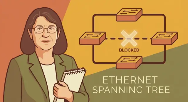
Radia Perlman’s Spanning Tree: The Quiet Backbone of Ethernet
Meet Radia Perlman and learn how Spanning Tree Protocol prevents Ethernet loops, enables redundancy, and made large networks stable and reliable.
Meet Radia Perlman and learn how Spanning Tree Protocol prevents Ethernet loops, enables redundancy, and made large networks stable and reliable.
Ethernet started as a simple way to connect computers in the same building. As it spread through offices, campuses, and data centers, expectations changed: local networks weren’t just “nice to have” anymore—they became the plumbing for email, file sharing, printers, phones, and eventually whole business workflows. When that plumbing failed, everything upstream failed with it.
Network builders also learned a hard reliability lesson: if you design a network with only one path between devices, a single broken cable or switch can take down an entire area. The obvious fix is redundancy—extra links and extra switches.
At Ethernet’s Layer 2, though, redundancy comes with a dangerous side effect: loops.
Radia Perlman designed the Spanning Tree Protocol (STP), the mechanism that lets Ethernet networks have redundancy without melting down from loops. Her contribution wasn’t “bigger pipes”—it was a practical, distributed way for switches to coordinate, agree on a safe forwarding structure, and automatically adapt when topology changes.
STP is the kind of system you only notice when it’s missing or misconfigured. When it’s working, nothing looks special: traffic flows, links stay up, and the network tolerates failures. It quietly blocks just enough paths to prevent loops, while keeping alternatives ready in case an active path breaks.
We’ll make the problem tangible by showing what an Ethernet loop looks like and why it causes storms and outages. Then we’ll walk through the core idea behind STP—how it keeps redundancy but eliminates loops—and explain, in plain terms, how switches decide which links forward and which ones wait in reserve. By the end, you’ll have an intuitive model for why STP became foundational to Layer 2 switching, and why Perlman’s design still matters even as Ethernet scaled far beyond its early office roots.
Early Ethernet networks were often small and straightforward: a handful of machines connected on a shared segment, or later, a few switches (and “bridges,” the older term) connecting segments together. If a single cable was unplugged, people noticed—but the failure was easy to understand.
As organizations added more rooms, floors, and buildings, the network rarely grew as a neat blueprint. It grew like a living thing: a new switch here, an “emergency” cable run there, a temporary workaround that quietly became permanent.
When networks expand this way, extra links get added for practical reasons:
Individually, each change can seem harmless. Collectively, they can create multiple paths between the same switches.
Redundancy is desirable because it improves uptime. If one link fails, traffic can take another route and users stay productive.
But at Layer 2 (switching), Ethernet was not designed to automatically “choose” one path and ignore the others. Switches forward frames based on learned addresses and, without a coordinating control, multiple paths can form a loop.
That’s the core tension: more cables can accidentally break the network. The very connections added to make things safer can create conditions where traffic circulates endlessly, overwhelming links and devices. Spanning Tree was created to keep the benefits of redundancy while preventing these accidental, network-wide self-inflicted outages.
An Ethernet switching loop happens when there are two (or more) active Layer 2 paths between the same switches—often because someone added a “backup” cable, plugged both uplinks into the same network, or connected switches in a ring without a control mechanism. Frames don’t have a hop limit at Layer 2, so they can circulate indefinitely.
Some traffic is meant to be flooded: broadcasts (like ARP requests) and “unknown destination” frames (when a switch doesn’t yet know which port leads to a MAC address). In a loop, that flooded frame gets copied and sent around the loop, then copied again, and again.
A simple example: a PC asks, “Who has 10.0.0.5?” via ARP (broadcast). With a loop, each switch repeats the broadcast out multiple ports, and the repeated copies keep arriving back at other switches. Very quickly, links and switch CPUs spend most of their time handling duplicates, leaving little room for real traffic.
Switches learn where devices are by watching which port a source MAC address arrives on. In a loop, the same device’s frames can arrive on different ports milliseconds apart. The switch keeps “changing its mind” about where that MAC lives, rewriting its table repeatedly. The result is traffic being forwarded to the wrong port, then flooded, then mislearned again.
These effects combine into symptoms people recognize: sudden network-wide slowdowns, intermittent disconnects, phones dropping calls, Wi‑Fi that “works but is unusable,” and sometimes a complete outage as switches saturate and stop responding. A single accidental patch cable can take down far more than the two devices it connects.
Ethernet gets its resilience from having more than one possible path between switches. If a cable is cut, traffic can take another route. The catch is that extra paths can accidentally form a circle—and Ethernet frames don’t have a “time to live” field to stop them from circulating forever.
Spanning Tree Protocol (STP) solves this with a simple bargain: keep the redundant links physically connected, but logically disable some of them so the active network forms a loop-free tree.
Think of a city that builds extra roads so ambulances can still reach every neighborhood when there’s a closure. If the city opens every road without rules, you can create confusing circular routes where drivers keep looping around the same blocks.
STP acts like traffic control:
A key part of Radia Perlman’s design is that it doesn’t rely on a controller telling every switch what to do. Each switch participates, exchanging small messages and independently reaching the same conclusion about which links should forward and which should wait in reserve.
That makes STP practical in real networks: you can add switches, remove links, or suffer failures, and the network converges on a safe forwarding pattern.
Done right, STP delivers two outcomes that normally conflict:
Spanning Tree Protocol (STP) has one job: keep Ethernet redundancy without letting traffic spin forever in a loop. It does that by making all switches agree on a single “best” set of links to use at any moment—called a spanning tree—and placing the extra links into a standby state.
STP first elects a root bridge, the switch chosen as the reference point for the whole network. Think of it as “the center of the map.” The root is determined by a priority value (configured or default) and a unique switch identifier; the lowest wins.
Every switch then asks: “What is my best path to the root?” STP assigns a path cost to each link (faster links usually get a lower cost). Each switch adds up costs along possible routes and chooses the lowest total as its preferred route to the root.
The port that a non-root switch uses to reach the root on that best route becomes its root port.
On each shared connection between switches (a “segment”), STP needs exactly one switch to forward traffic toward the root. That forwarding port is the designated port for the segment. The switch advertising the lowest-cost path to the root on that segment gets the designated role.
Ports that are not chosen as a root port or a designated port are placed into blocking (STP) or a similar non-forwarding state (newer variants). Blocking does not remove the cable or eliminate redundancy—it simply stops that port from forwarding regular Ethernet frames, so a loop can’t form. If an active link fails, STP can unblock a backup path and keep the network connected.
Let’s make STP concrete with a tiny network of four switches:
STP starts by choosing a single reference point: the root bridge (root switch). Each switch advertises an identifier (the “bridge ID”), and the lowest ID wins.
Assume S1 has the lowest bridge ID. Now everyone agrees: S1 is the root.
Every non-root switch picks exactly one port as its root port: the port that provides the best path back to S1.
For each link segment, STP picks one side to be the designated port (the side that should forward traffic for that segment). Any port that is neither a root port nor a designated port becomes blocking.
In this example, the link S3–S4 is where the loop gets cut. If S3 already reaches the root via S2, STP can put S3’s port toward S4 (or S4’s port toward S3, depending on tie-breaks) into blocking.
Result: you still have all cables plugged in, but there’s only one active path between any two points—no loop.
If the active path breaks (say S2–S3 goes down), STP re-evaluates. The previously blocked link S3–S4 can transition to forwarding, restoring connectivity via S3 → S4 → S1.
That change isn’t instant; STP needs time to recover (convergence) to safely update the forwarding state without reintroducing loops.
Spanning Tree only works if every switch in the network agrees on the same rules. That’s why standards matter: most real networks are multi-vendor, built from whatever was purchased over many years. Without a shared protocol, one brand’s “loop prevention” feature might not understand another’s, and redundancy could turn into an outage.
The traditional Spanning Tree Protocol is defined in IEEE 802.1D. You don’t need to read the clauses to benefit from it—the key point is that 802.1D gives different vendors a common language for how to elect a root bridge, calculate path cost, and decide which ports should forward or block.
Even when you later move to newer variants (like RSTP or MSTP), the reason upgrades are possible is the same: the behavior is standardized enough that devices can coordinate rather than guess.
Switches coordinate using small control frames called BPDUs (Bridge Protocol Data Units). Think of BPDUs as STP’s “hello messages”: they carry the facts switches need to build a shared view of the topology—who they believe the root is, how far away it is (cost), and timing information.
Because BPDUs are exchanged continuously, STP can react when something changes. If a link fails, the BPDU conversation changes too, and switches can reconverge and open a previously blocked path.
One practical wrinkle: vendors often use different names for the same knobs. A setting like “port cost,” “edge/portfast,” or “bpdu guard” might appear under different menus or be worded differently. The underlying STP concepts are consistent, but the interface vocabulary isn’t—so it helps to translate features back into what 802.1D is trying to accomplish.
Classic STP (IEEE 802.1D) solved loops, but it could be painfully slow to “heal” after a link or switch failure. The reason is simple: STP was cautious. Ports didn’t start forwarding right away—they walked through timed states (blocking → listening → learning → forwarding). With default timers, reconvergence could take tens of seconds (often ~30–50 seconds), long enough for voice calls to drop, applications to time out, or users to assume “the network is down.”
Rapid Spanning Tree Protocol (RSTP, IEEE 802.1w) keeps the same goal—loop-free forwarding with redundancy—but changes how switches reach agreement.
Instead of waiting out long, fixed timers, RSTP uses a quicker handshake between switches to confirm which ports can safely forward. It also recognizes that some ports should move immediately:
In plain terms: RSTP still blocks the right links to prevent loops; it just stops treating every change like a worst-case event.
As networks grew, running a single tree for everything became limiting—especially with many VLANs and complex topologies. Multiple Spanning Tree Protocol (MSTP, IEEE 802.1s) lets you create multiple spanning-tree instances, and map groups of VLANs to each instance.
That means you can:
The headline improvement across STP → RSTP → MSTP is consistent: keep redundancy, prevent loops, and restore forwarding faster and more predictably.
Spanning Tree’s most underappreciated benefit is how it turns “extra cables and switches” into predictable reliability. At enterprise scale—many closets, many access switches, constant moves/adds/changes—Layer 2 redundancy can be a gift or a trap. STP makes it more likely to be the first.
Large networks rarely fail because one link is cut; they fail because recovery is messy. STP helps by providing a controlled way for the network to react when something changes:
Many organizations keep STP enabled even if they think their topology is loop-free. The reason is pragmatic: people make mistakes, documentation drifts, and unexpected Layer 2 paths appear. With STP on, an accidental extra patch cord is more likely to cause a blocked port than a building-wide outage.
Modern data centers often prefer routed leaf–spine fabrics (Layer 3) or specific Layer 2 multi-path technologies to get active/active bandwidth without relying on classic STP convergence. That said, STP (or variants like RSTP/MSTP) is still widely used in campus networks, in edge segments, and as a compatibility layer where pure Layer 3 isn’t practical.
At scale, STP’s real achievement is operational as much as technical: it makes redundancy manageable for ordinary teams, not just specialists.
Spanning Tree is simple in concept—prevent Layer 2 loops while keeping backup paths—but a few persistent myths make people disable it, misconfigure it, or “optimize” it into an outage.
It’s true that modern networks often rely on Layer 3 routing, MLAG, and overlay designs that reduce the need for classic IEEE 802.1D. But STP (or its newer forms like RSTP/MSTP) still adds a safety net anywhere Ethernet can accidentally form a loop: access switches, temporary event networks, labs, small branch sites, and any environment where someone might patch two ports together “just to test.”
Disabling STP can turn a harmless cabling mistake into a broadcast storm that takes down an entire VLAN.
A blocked port isn’t “dead.” It’s a pre-validated standby path. STP intentionally trades some active capacity for stability: if the forwarding link fails, the blocked link can become the new path without a human racing to re-cable.
Teams sometimes try to force all links to forward by turning off STP, flattening VLANs, or adding unmanaged switches. That may look efficient—until the first loop melts the network.
Redundancy helps only when it’s designed. Adding extra cross-links between switches without planning increases the number of possible loop scenarios and makes STP behavior harder to predict. The result can be unexpected traffic paths, blocked uplinks, or longer reconvergence after a failure.
Even with STP enabled, bad settings can cause real damage:
The takeaway: STP isn’t just a checkbox—it’s a control plane. Treat it like one, document intent, and validate changes before rolling them broadly.
Spanning Tree issues often show up as “the network is slow” before anyone realizes there’s a Layer 2 problem. A few focused checks can save hours of guesswork.
When an Ethernet loop or STP instability appears, you’ll commonly see:
Start with the fundamentals:
Good STP hygiene is mostly process:
If you want a broader checklist for isolating network issues beyond STP, see /blog/network-troubleshooting-basics.
STP is a great example of “quiet infrastructure,” and it tends to fail in very human ways: unclear intent, undocumented cabling, inconsistent configs, and ad-hoc troubleshooting. One practical way to reduce that risk is to build lightweight internal tools and runbooks around your STP operations.
With Koder.ai, teams can vibe-code small web dashboards or utilities from a simple chat—like a tool that ingests switch outputs, highlights the current root bridge, flags unexpected blocking ports, or tracks topology-change events over time. Because Koder.ai supports exporting source code and deploying/hosting apps (with rollback and snapshots), it’s also a convenient way to turn “tribal knowledge” into a maintained internal service rather than a one-off script on someone’s laptop.
Radia Perlman’s spanning tree work is a reminder that some of the most important infrastructure doesn’t look flashy—it simply prevents chaos. By giving Ethernet a practical way to use redundant links without creating loops, STP helped make “add a backup path” a safe default rather than a risky experiment. That shift enabled larger, more resilient Layer 2 networks in enterprises, campuses, and data centers.
STP assumes something will go wrong: a cable gets plugged into the wrong port, a switch reboots, a link flaps. Instead of hoping operators never make mistakes, it builds a system that can absorb mistakes and still converge to a safe state. The lesson is broader than networking: treat failure modes as first-class requirements.
Spanning tree intentionally blocks some links so the overall network remains stable. That “wasted capacity” is a trade-off in service of predictable behavior. Good systems often reserve headroom—extra time, extra checks, extra guardrails—because avoiding catastrophic failure is worth more than squeezing out the last percent of utilization.
STP works because every switch follows the same distributed rules and exchanges small control messages to agree on a loop-free topology. You don’t need one operator manually deciding which ports to shut down during every change. The takeaway: when many components must cooperate, invest in protocols and defaults that make the safe behavior the easiest behavior.
If you remember only a few points, make them these: build redundancy, assume human error, and automate the “safe choice.” That mindset—more than any single feature—explains why spanning tree became such a quiet essential.
If you want more approachable networking fundamentals, browse /blog.
A Layer 2 loop happens when switches have two or more active paths between the same segments, creating a cycle. Because Ethernet frames don’t have a hop limit at Layer 2, flooded traffic (broadcasts and unknown unicasts) can circulate indefinitely and multiply, overwhelming links and switch CPUs.
Redundancy adds alternate paths, but without coordination, switches may forward on all of them. That creates a loop where flooded frames get replicated repeatedly, leading to broadcast storms and unstable MAC learning—often resulting in network-wide outages from a single extra patch cable.
STP keeps redundant links physically present but logically disables some ports so the active topology becomes a loop-free tree. If an active path fails, STP can transition a previously blocked port to forwarding to restore connectivity.
STP elects a root bridge as a reference point for the whole Layer 2 domain. The switch with the lowest bridge ID (priority + unique identifier) becomes root; choosing the intended core/distribution switch as root helps keep traffic paths predictable.
Each non-root switch selects one root port: the port with the lowest total path cost back to the root. Path cost is based on link speed (faster links typically have lower cost), and tie-breakers use IDs to make the choice deterministic.
On every switch-to-switch segment, STP selects one designated port to forward for that segment (the side advertising the best path to the root). Any port that is neither a root port nor a designated port becomes blocking/discarding, which is how STP breaks loops.
It means the port does not forward normal user traffic frames, so it can’t participate in a loop. The link still stays up and can carry STP control traffic; if topology changes (like a failure), that blocked port may be promoted to forwarding as the new active path.
BPDUs (Bridge Protocol Data Units) are STP control frames switches send to share topology info: who they think the root is, their path cost to it, and timing details. By continuously exchanging BPDUs, switches can detect failures/changes and reconverge on a safe loop-free topology.
Classic STP (IEEE 802.1D) can take tens of seconds to reconverge because it relies on conservative timers and port states. RSTP (802.1w) speeds this up with faster handshakes and rapid transitions (especially for edge/PortFast-type ports), reducing downtime after failures.
A practical checklist is:
For broader diagnostics beyond STP, see /blog/network-troubleshooting-basics.