

STMicroelectronics Platforms & Sensors: Cars, IoT, Industry
Learn how STMicroelectronics embedded platforms, MCUs, and sensor ecosystems support automotive safety, IoT products, and industrial control systems.
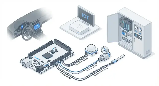
What ST Platforms and Sensor Ecosystems Mean
An embedded platform is the “kit of parts” you build an electronic product around. It usually includes a main chip (a microcontroller or processor), supporting components (power, clocks, connectivity), reference designs, and the software tools and libraries needed to get from idea to working device.
A sensor ecosystem is the matching set of sensors (motion, pressure, temperature, and more) plus the drivers, calibration guidance, example code, and sometimes pre-built algorithms that turn raw readings into useful information.
Why platforms matter
Platforms matter because they let teams reuse proven building blocks instead of reinventing the basics each time.
When you stay within a well-supported platform family, you typically get:
- Faster development: ready-to-use firmware libraries, evaluation boards, and example projects speed up prototyping.
- Easier scaling: you can move from a low-cost device to a higher-performance version without rewriting everything.
- More predictable production: reference designs and validated combinations reduce surprises when you transition from prototype to manufacturing.
For STMicroelectronics specifically, “platform” often means a combination of STM32 (MCUs), STM32MPx (MPUs), connectivity chips/modules, power solutions, and development tools, while the sensor ecosystem commonly includes ST MEMS sensors and supporting software for motion processing and environmental measurements.
What to expect in this guide
This article focuses on the common ST building blocks and how they fit together in real products: compute (MCU/MPU), sensing (MEMS and environmental), connectivity, power, and security. The goal isn’t to catalog every part number, but to help you understand the “system thinking” behind selecting compatible components.
How this maps to cars, IoT, and factories
- Cars (automotive electronics) often prioritize safety, reliability, and in-vehicle networking—sensors feed critical functions like stability, comfort, and monitoring.
- IoT edge devices usually optimize for low power, small size, and a smooth user experience—sensors and wireless links must be efficient.
- Industrial automation emphasizes determinism, long lifetimes, and resilience in harsh environments—platform choices need to remain stable for years.
With those three domains in mind, the rest of the sections show how ST’s platform approach helps you assemble systems that are easier to build, validate, and maintain.
Core Building Blocks: MCUs, MPUs, and Peripherals
When people talk about an “ST platform,” they’re usually describing a compute core (MCU or MPU) plus the peripherals and software support that make the whole device practical. Picking the right core early prevents painful redesigns later—especially when sensors, connectivity, and real-time behavior are involved.
MCUs vs. MPUs: who does what?
Microcontrollers (MCUs)—for example, many STM32 families—are a strong fit for control loops, reading sensors, driving motors, managing simple user interfaces, and handling common connectivity (BLE/Wi‑Fi modules, CAN transceivers, etc.). They typically boot fast, run one main firmware image, and excel at predictable timing.
Microprocessors (MPUs)—such as STM32MP1-class devices—are used when you need heavier data processing, rich graphics UI, or Linux-based networking stacks. They can simplify “app-like” features (web UI, logging, file systems), but often increase power needs and software complexity.
Peripherals that can decide the whole design
The core is only half the story; the peripheral set often drives selection:
- ADC/DAC for analog sensors, battery monitoring, and audio/control outputs
- Timers and PWM for motors, LEDs, power stages, and precise sampling
- CAN (and automotive variants) for vehicle networks and industrial nodes
- SPI / I2C for sensors, memories, and expansion chips
- USB for data, power, device configuration, or firmware updates
If your design needs multiple high-speed SPI buses, synchronized PWM, or a specific CAN feature, that can narrow the options faster than CPU speed.
Real-time behavior: latency and determinism
Real-time isn’t just “fast.” It’s consistent. Control systems care about worst-case latency, interrupt handling, and whether sensor reads and actuator outputs happen on schedule. MCUs with well-designed interrupts and timers are usually the simplest path to determinism; MPUs can do it too, but it typically requires more careful OS and driver tuning.
Compute choice impacts BOM, power, and firmware
A higher-end processor can reduce external chips (fewer companion ICs) or enable richer features, but it may raise power budget, thermal constraints, and firmware effort (boot chain, drivers, security updates). A simpler MCU can lower BOM and power, but might push complexity into firmware optimization or dedicated accelerators/peripherals.
Sensor Portfolio Basics: From MEMS to Environmental Sensing
STMicroelectronics’ sensor lineup is broad enough that you can build everything from a smartwatch to a vehicle stability system without mixing vendors. The practical value is consistency: similar electrical interfaces, software support, and long-term availability, even as products scale from prototypes to volume.
Common sensor types you’ll run into
Most embedded products start with a small set of “workhorse” sensors:
- Accelerometers and gyroscopes (IMUs): detect motion, vibration, tilt, and rotation for features like step counting, anti-tamper, tool tracking, and vehicle dynamics.
- Pressure sensors: used for altitude estimation, HVAC monitoring, water-level and pump control, and leak detection.
- Temperature sensors: support thermal protection, calibration, and comfort/quality monitoring.
- Magnetic sensors (magnetometers): enable compass heading, lid/open-close detection, and rotary position sensing with magnets.
- ToF/proximity sensors: measure distance or presence for gesture control, wake-on-approach, and people/object detection.
What “MEMS” means (and why it’s everywhere)
MEMS stands for micro-electro-mechanical systems: tiny mechanical structures manufactured on silicon, often packaged like an IC. MEMS enables compact, low-power sensors that fit in phones, earbuds, wearables, and dense industrial nodes. Because the sensing element is small and mass-producible, MEMS is a good match for products that need reliable performance at reasonable cost.
The specs buyers compare (and what they really affect)
When selecting sensors, teams commonly compare:
- Range: maximum measurable acceleration/rotation/pressure; too low saturates, too high can reduce resolution.
- Noise: impacts how “stable” readings look at rest; critical for motion tracking and low-amplitude vibration.
- Drift (especially gyros): affects long-term accuracy and how often you need correction.
- Bandwidth: how fast the sensor can respond to changes; important for control loops and vibration analysis.
- Sampling rate (ODR): how many readings per second; affects responsiveness and power.
Practical trade-offs: accuracy, cost, power, placement
Better specs can cost more and draw more power, but mechanical placement can matter just as much. For example, an IMU mounted far from the center of rotation or near a vibrating motor may need filtering and careful board design to reach its potential. In compact devices, you’ll often choose a slightly lower-power sensor and invest in placement, calibration, and firmware smoothing to hit the user experience target.
Sensor Fusion and Edge Intelligence
Raw sensor signals are noisy, biased, and often ambiguous on their own. Sensor fusion combines readings from multiple sensors—typically an accelerometer, gyroscope, magnetometer, pressure sensor, and sometimes GNSS—into a cleaner, more meaningful estimate of what’s happening: orientation, motion, steps, vibration severity, or a “still/moving” decision.
Why raw signals aren’t enough
A single MEMS accelerometer can tell you acceleration, but it can’t separate gravity from motion during quick movements. A gyro tracks rotation smoothly, but its estimate drifts over time. A magnetometer helps correct long-term heading drift, but it’s easily disturbed by nearby metal or motors. Fusion algorithms balance these strengths and weaknesses to produce stable results.
Practical examples you’ll recognize
- Orientation tracking: phones, wearables, drones, and in-cabin automotive controls use fused 6-axis/9-axis data for responsive, stable attitude.
- Vibration monitoring: industrial sensors can fuse high-rate vibration with temperature and operating states to distinguish “normal vibration” from bearing wear.
- Motion detection: ultra-low-power “wake on motion” can run on the sensor hub/MCU, keeping the main processor asleep.
- Dead-reckoning aids: short GNSS dropouts can be bridged by IMU-based motion estimates (useful in tunnels or dense urban areas).
Edge processing vs sending raw data
Running fusion at the edge (on an ST MCU, an embedded sensor hub, or a smart MEMS device) cuts bandwidth dramatically: you transmit “tilt = 12°” instead of thousands of samples per second. It also improves privacy, because you can keep raw motion traces on-device and send only events or aggregated metrics.
Calibration and filtering: the difference between demos and deployments
Reliable fusion depends on calibration (offsets, scale factors, alignment) and filtering (low-pass/high-pass, outlier rejection, temperature compensation). In real products, you’ll also plan for magnetic interference, mounting orientation changes, and manufacturing variation—otherwise the same device can behave differently across units or over time.
Automotive: Safety, Reliability, and Vehicle Networks
Cars are a special kind of embedded environment: they’re electrically noisy, exposed to wide temperature swings, and expected to work consistently for many years. That’s why automotive-focused MCUs, sensors, and power components are often selected as much for their qualifications, documentation, and long-term availability as for raw performance.
Typical automotive use cases
STMicroelectronics platforms often show up in multiple “zones” of a vehicle:
- Body control and comfort: door modules, lighting control, seat functions, window lifters, and climate control interfaces.
- Infotainment controls: steering-wheel buttons, rotary knobs, haptic inputs, and sensor-driven user interactions.
- Driver assistance support components: sensor interfaces, timing and monitoring tasks, and deterministic control loops that help larger ADAS computers by handling local I/O.
- Monitoring: battery/voltage sensing, temperature tracking, motor current measurement, and system health checks.
Vehicle networks: CAN and LIN in plain terms
Most automotive ECUs don’t operate alone—they communicate over in-vehicle networks:
- LIN is commonly used for simpler, lower-speed nodes (for example, a door module). It’s cost-effective and works well for “one master, many slaves” setups.
- CAN is used for faster, more critical communication among ECUs. It supports multi-node messaging and stronger error handling.
For an MCU, built-in CAN/LIN support (or easy pairing with transceivers) affects not only wiring and cost, but also timing behavior and how cleanly the ECU integrates into the vehicle.
Reliability constraints and the role of safety processes
Automotive designs must tolerate temperature range, EMI/EMC exposure, and long service lifetimes. Separately, functional safety is a development approach: it emphasizes disciplined requirements, analysis, testing, and tool support so that safety-related functions are engineered and verified systematically. Even when your feature isn’t “safety-critical,” adopting parts of that process can reduce late-stage surprises and rework.
IoT Devices: Power, Size, and User Experience
Most IoT products succeed or fail on the “unsexy” constraints: battery life, enclosure size, and whether the device feels responsive and trustworthy. STMicroelectronics platforms and sensor ecosystems are often chosen here because they let teams balance sensing accuracy, local compute, and connectivity without overbuilding the hardware.
A typical IoT architecture (and where ST parts fit)
A practical IoT pipeline usually looks like: sensing → local compute → connectivity → cloud/app.
Sensors (motion, pressure, temperature, bio signals) produce raw data. A low-power MCU handles filtering, thresholds, and simple decision-making so the radio only transmits when needed. Connectivity (Bluetooth LE, Wi‑Fi, sub‑GHz, cellular, or LoRa) then moves selected data to a phone or gateway, which forwards it to an app or cloud service for dashboards and alerts.
The key idea: the more you can decide locally, the smaller the battery and the cheaper the connectivity can be.
Power budget thinking: sleep, duty cycle, wake-on-event
Battery life is rarely about peak current; it’s about time spent asleep. Good designs start with a budget: how many minutes per day can the device be awake, sampling, processing, and transmitting?
- Sleep modes keep the MCU in a deep low-power state most of the time.
- Duty cycles define how often you sample (e.g., take a temperature reading every 10 minutes vs. every 10 seconds).
- Wake-on-event uses interrupts (for example from a motion sensor) so the system only wakes when something meaningful happens.
This is where sensor features matter as much as the MCU: a sensor that can detect an event on its own prevents the main processor and radio from waking unnecessarily.
Examples that make the trade-offs concrete
- Smart locks: fast wake-up and reliable motion/touch detection feel “instant.” False triggers drain batteries and annoy users.
- Wearables: sensor quality affects step counts, heart-rate stability, and perceived accuracy; poor filtering leads to noisy graphs and lost trust.
- Asset trackers: location and motion features must be tuned to avoid constant reporting (expensive) while still catching real movement.
- Home sensors: temperature/humidity nodes can run for years if sampling is sensible and transmissions are batched.
How sensor choice shapes user experience
UX isn’t just the app—it’s how the device behaves. A motion sensor that triggers on vibration can cause phantom alerts; an environmental sensor with slow response can miss real changes; and a marginal power design can turn a “one-year battery” promise into three months.
Choosing sensors and MCUs together—based on noise, latency, and low-power capabilities—helps you deliver a device that feels responsive, avoids false alarms, and meets battery-life expectations without increasing size or cost.
Industrial Control: Determinism, Harsh Environments, Longevity
Industrial control is less about flashy features and more about predictable behavior over long periods. Whether you’re building a PLC-adjacent module, a motor drive, or a condition-monitoring node, the platform choice needs to support deterministic timing, survive noisy environments, and remain serviceable for years.
Where ST platforms show up in industrial systems
A common pattern is a microcontroller-based “sidecar” to a PLC: adding extra I/O, specialized measurement, or connectivity without redesigning the whole control cabinet. ST MCUs are also widely used in motor control (drives, pumps, conveyors), metering, and condition monitoring—often combining real-time control loops with sensor acquisition and local decision-making.
Determinism: timing you can trust
Deterministic control means your sampling, control loop execution, and outputs happen when expected—every cycle. Practical enablers include:
- Hardware timers and PWM units for precise motor control and actuator timing
- Fast, predictable interrupt handling for sampling and safety reactions
- ADCs and comparators for tight measurement-to-action paths (for example, current sensing)
The design goal is to keep time-critical tasks stable even when communications, logging, or user interfaces get busy.
Harsh environments: vibration, dust, and electrical noise
Industrial sites add mechanical stress and electrical interference that consumer devices rarely face. Key concerns are vibration (especially around motors), dust and moisture ingress, and electrical noise from switching loads. Sensor selection and placement matter here—accelerometers for vibration monitoring, current/voltage sensing for drives, and environmental sensors when enclosure conditions affect reliability.
Integration essentials: isolation, analog front ends, signal integrity
Many industrial signals can’t be wired straight into a microcontroller.
- Isolation: needed when interfacing to high-voltage domains or noisy field wiring (to protect people and electronics).
- Analog front ends (AFEs): condition low-level sensor outputs, handle filtering, and scale signals into an ADC-friendly range.
- Signal integrity: layout, grounding, and filtering reduce EMI-induced false readings—critical for stable control and trustworthy diagnostics.
Longevity and maintainability
Industrial deployments must plan for long service life: spare units, component availability, and firmware updates that don’t disrupt operations. A practical lifecycle approach includes versioned firmware, safe update mechanisms, and clear diagnostics so maintenance teams can troubleshoot quickly and keep equipment running.
Connectivity Choices Across Cars, IoT, and Factories
Connectivity is where an embedded platform stops being “a board with sensors” and becomes part of a system: a vehicle network, a building full of devices, or a production line. ST-based designs typically pair MCUs/MPUs with one or more radios or wired interfaces depending on the job.
Common options (and what they’re good at)
BLE is a great fit for short-range links to phones, commissioning tools, or nearby hubs. It’s usually the easiest path to low power, but it’s not meant for high data rates over long distances.
Wi‑Fi delivers higher throughput for direct-to-router devices (cameras, appliances, gateways). The trade-off is power draw and more demanding antenna/enclosure work.
Ethernet is the factory favorite for dependable wired throughput and predictable behavior. It’s also common in vehicles (as Automotive Ethernet) as bandwidth needs grow.
Cellular (LTE-M/NB-IoT/4G/5G) is for wide-area coverage when there is no local infrastructure. It adds cost, certification effort, and power considerations—especially for always-on use.
Sub‑GHz (e.g., 868/915 MHz) targets long range at low data rates, often for sensors that report small packets infrequently.
How to choose: range, throughput, power, and rules
Start with range and message size (a temperature reading vs. audio streaming), then validate battery life and peak current needs. Finally, account for regional regulations (licensed cellular vs unlicensed sub‑GHz limits, channel plans, transmit power, duty cycle).
Gateway vs direct-to-cloud
A local gateway makes sense when you want ultra-low-power endpoints, need to bridge protocols (BLE/sub‑GHz to Ethernet), or need local buffering when the internet drops.
Direct-to-cloud simplifies architecture for single devices (Wi‑Fi/cellular), but pushes complexity into power design, provisioning, and ongoing connectivity costs.
Practical design implications: antennas and enclosures
Antenna performance can be ruined by metal housings, batteries, cable bundles, or even the user’s hand. Plan for clearance, choose materials carefully, and test early with the final enclosure—connectivity problems are often mechanical, not firmware-related.
Security and Device Lifecycle: From Boot to Updates
Security isn’t a single feature you “add later.” With embedded platforms and sensors, it’s a chain of decisions that starts the moment a device powers on and continues through every firmware update until the product is retired.
Security building blocks (practical view)
A common foundation is secure boot: the device verifies that the firmware is authentic before it runs. On ST platforms this is often implemented with a hardware root of trust (for example, MCU security features and/or a dedicated secure element) plus signed images.
Next is key storage. Keys should live in places designed to resist extraction—either protected MCU regions or a secure element—rather than in plain flash. That enables encrypted firmware updates, where the device both validates a signature (integrity/authenticity) and can decrypt the payload (confidentiality) before installing it.
Why threat models change by domain
Consumer IoT devices often face large-scale, remote attacks (botnets, credential stuffing, cheap physical access). Industrial systems are more concerned with targeted disruption, downtime, and long service lives where patch windows are limited. Automotive electronics must handle safety-adjacent risks, complex supply chains, and strict control over who can update what—especially when multiple ECUs share vehicle networks.
Lifecycle thinking: provisioning to decommissioning
Plan for provisioning (injecting keys/identities during manufacturing), updates (A/B swap or rollback protection to avoid bricking), and decommissioning (revoking credentials, wiping sensitive data, and documenting end-of-support behavior).
What to document for compliance (without overpromising)
Keep clear records of: your threat model, secure boot/update flow, key management and rotation approach, vulnerability intake and patch policy, SBOM, and test evidence (penetration results, fuzzing notes, secure coding practices). Describe what you do and measure—avoid claiming certifications unless you’ve formally completed them.
Power Management and Thermal Design Practicalities
Power and heat are tightly linked in embedded products: every wasted milliwatt becomes temperature rise, and temperature directly affects sensor accuracy, battery performance, and long-term reliability. Getting this right early saves painful board spins later.
Power rails: the “shape” of your energy
Most designs end up with a small set of rails: a battery/input rail, one or more regulated rails for logic (often 3.3 V and/or 1.8 V), and sometimes a higher rail for actuators or displays.
A few practical rules of thumb:
- Buck regulators are the default when stepping down from a higher voltage (e.g., 12 V, 5 V) efficiently.
- Boost regulators help when the battery can dip below your required rail (common with coin cells or single-cell Li-ion near end-of-charge).
- Buck-boost is useful when the input can be above and below the target voltage across operating range.
- LDOs are simple and quiet (great for sensitive analog or RF rails), but waste power proportional to voltage drop—so use them strategically.
Battery management basics: choose protection/charging that matches chemistry, and budget for brownout behavior (what happens to the MCU, sensors, and memory when the battery sags).
Peak vs average current: sensors and radios set the traps
Many products miss their battery-life target because they design for average current and forget peaks:
- Radios (BLE, Wi‑Fi, cellular) draw short, high bursts during transmit/receive and association.
- Sensors can spike during startup, high-performance modes, or when running at higher ODR (output data rate).
Your regulators and decoupling must handle peaks without droop, while firmware must keep the average low via sleep modes and duty cycling.
Thermal: enclosure + ambient + duty cycle
Heat isn’t only about the chip. The enclosure material, airflow, and mounting surface often dominate. Always sanity-check:
- Worst-case ambient temperature (factory cabinets and cars can be far hotter than a lab).
- Duty cycle (continuous radio streaming vs occasional bursts).
- Local hotspots from regulators, power switches, or RF PA stages.
Quick checklist: better battery life without losing responsiveness
- Measure real workloads (not “typical”) and log peak/average current.
- Keep sensors in low-power mode; temporarily boost ODR only when needed.
- Batch and compress data before radio upload; avoid frequent reconnects.
- Use interrupts (motion/threshold) instead of constant polling.
- Validate regulator efficiency at your real load currents (especially light-load).
Prototyping to Production: Ecosystem Tools and Validation
Getting a prototype working is only the start. The real time-saver is using the ecosystem around ST platforms to reduce rework before you commit to a PCB spin, certifications, or a manufacturing run.
Speed up development with ready-made building blocks
ST’s evaluation boards and example projects let you prove the idea quickly while keeping a path to production:
- Nucleo / Discovery boards for STM32 bring a stable baseline for compute, debug, and power measurements.
- Sensor expansion boards (X-NUCLEO) and SensorTile-style kits help you validate motion and environmental sensing without designing analog front-ends from scratch.
- Reference designs and STM32Cube packages provide working firmware patterns (drivers, middleware, demo apps) that you can later trim down for your product.
Treat these as “learning hardware”: document what you change, and keep a list of assumptions you still need to verify on your own board.
Don’t forget the software around the device
Even when the embedded side is “done,” most products still need a companion layer: provisioning screens, dashboards, logs, alerting, and simple APIs for manufacturing and field support. Teams often underestimate this work.
This is a good place to use a vibe-coding workflow like Koder.ai: you can generate a lightweight web dashboard, a small Go + PostgreSQL backend, or a Flutter mobile companion app from a chat-based spec, then iterate quickly as your on-device telemetry and requirements evolve. It’s especially useful during pilot runs when you’re constantly adjusting what to log and how to visualize it.
Validate the risky stuff early (before hardware freezes)
Some failures only show up once the device is physically real:
- Sensor performance in the enclosure: mounting, adhesives, vibration paths, and air flow can change readings (especially for motion and environmental sensors).
- RF range in real locations: test with the final antenna area, plastics, cable routing, and typical user positions.
- Power measurements: measure sleep, wake spikes, radio bursts, and sensor sampling cycles; battery life estimates based on averages often mislead.
Avoid prototype-to-production pitfalls
Common traps include component availability, missing test points (SWD, power rails, sensor interrupts), and no plan for manufacturing tests (programming, calibration, basic RF/sensor checks). Designing with test and calibration in mind saves days per batch.
Define pilot acceptance criteria
Set pass/fail criteria for a pilot run upfront: KPIs (battery life, reconnect time, sensor drift, false alarms), and a simple field data plan (what you log, how often, and how you retrieve it). This turns pilot feedback into decisions, not opinions.
How to Choose the Right Platform and Sensors (Checklist)
Picking an MCU/MPU platform and a sensor set is easiest when you treat it like a funnel: start wide with needs, then narrow with constraints, then validate with real tests.
Step-by-step selection flow
- Requirements (what “good” looks like)
Define measurable targets: sensing range, accuracy, latency, sampling rate, operating temperature, lifetime, and any standards you must meet.
- Constraints (what you can’t change)
List hard limits: BOM cost, battery life, PCB area, enclosure material, interfaces available (I²C/SPI/CAN/Ethernet), and regulatory needs.
- Shortlisting (compatible combinations)
Shortlist 2–3 platform + sensor “bundles” that match interfaces and power budgets. Include the software story: available drivers, middleware, reference designs, and whether you’ll run sensor fusion on the device or offload it.
- Prototype tests (prove it early)
Run quick experiments: motion/temperature sweeps, vibration tests, EMC exposure (even informal), and accuracy checks against a known reference. Measure power in realistic duty cycles—not just datasheet “typical.”
Common mistakes to avoid
- Over-specifying sensors: paying for precision you can’t use because of mechanical mounting, noise, or poor placement.
- Ignoring calibration: assuming factory specs hold after assembly, temperature shifts, or aging.
- Underestimating the update strategy: no plan for firmware updates, configuration management, or field diagnostics.
A simple decision matrix template
| Criterion | Option A | Option B | Notes |
|---|---|---|---|
| Cost (BOM + manufacturing) | Include test time and connectors | ||
| Power (active + sleep) | Use your real duty cycle | ||
| Accuracy & drift | Consider calibration effort | ||
| Compute headroom | Fusion, filtering, ML, safety margin | ||
| Connectivity fit | Bandwidth, latency, coexistence | ||
| Security & lifecycle | Secure boot, keys, updates |
Next actions checklist
- Write a one-page requirements sheet with pass/fail tests.
- Pick two candidate bundles and prototype both.
- Verify calibration and mechanical placement early.
- Define your update path (and who owns it) before production.
- Capture results in the matrix and make the trade-offs explicit.
FAQ
What does “embedded platform” mean in the STMicroelectronics context?
An embedded platform is the reusable foundation for a product: a main compute device (MCU/MPU), supporting components (power, clocks, connectivity), plus development tools, reference designs, and firmware libraries.
Using a consistent platform family usually reduces redesign risk and speeds up prototyping-to-production.
What is a “sensor ecosystem,” and why does it matter?
A sensor ecosystem is more than sensor part numbers. It includes drivers, example code, calibration guidance, and sometimes ready-made algorithms that convert raw data into usable outputs (events, orientation, metrics).
The benefit is faster integration and fewer surprises when you scale from prototype to volume.
How do I decide between an STM32 MCU and an STM32MPx MPU?
Pick an MCU when you need:
- Fast boot and simple firmware deployment
- Predictable real-time timing (control loops, motor control, sensor sampling)
- Lower power and typically lower system complexity
Pick an MPU when you need:
- Linux and richer networking stacks
- Heavier data processing, file systems, or complex UIs
- More “application-like” software features (at the cost of higher complexity/power)
Which peripherals most often decide the MCU/MPU choice?
Often the peripheral set narrows your options faster than CPU speed. Common “design-deciders” include:
- ADC/DAC needs (channels, speed, accuracy)
- Timer/PWM requirements (synchronized outputs, motor-control features)
- CAN/LIN availability for automotive/industrial networking
- Number and speed of SPI/I²C buses for sensors and memories
- USB role (power, data, configuration, firmware updates)
What does “determinism” mean, and how do I design for it?
Real-time means consistent worst-case timing, not just high performance. Practical steps:
- Use hardware timers/PWM for time-critical actuation
- Structure interrupt priorities around sampling and safety reactions
- Keep “non-real-time” work (logging, UI, communications) from blocking control loops
MCUs are often the simplest path to determinism; MPUs can work too, but typically need more OS/driver tuning.
What are MEMS sensors, and why are they so widely used?
MEMS (micro-electro-mechanical systems) are tiny mechanical sensing structures built on silicon and packaged like ICs.
They’re popular because they’re compact, low power, and cost-effective—ideal for wearables, phones, dense industrial nodes, and many automotive sensing tasks.
Which sensor specs matter most in real products?
Focus on what changes your system behavior:
- Range: too low saturates; too high can reduce usable resolution
- Noise: affects stability at rest and low-amplitude vibration detection
- Drift (gyros): drives how often you need correction/fusion
- Bandwidth/ODR: affects responsiveness, vibration analysis, and power
Then validate with your real mechanical mounting and enclosure—placement can dominate datasheet differences.
What is sensor fusion, and when do I need it?
Fusion combines sensors (often accel + gyro + magnetometer, sometimes pressure/GNSS) to produce stable, meaningful outputs like orientation, steps, vibration severity, or still/moving decisions.
It helps because each sensor has weaknesses alone (e.g., gyro drift, magnetometer interference, accelerometer gravity ambiguity). Fusion balances those errors.
Why process sensor data at the edge instead of sending raw data to the cloud?
Edge processing reduces bandwidth and power by sending results instead of raw streams (e.g., “tilt = 12°” or “event detected” rather than thousands of samples).
It can also improve privacy by keeping raw motion traces on-device and transmitting only events or aggregated metrics.
What security basics should I plan for from boot to firmware updates?
Treat security as a lifecycle:
- Secure boot to ensure only authenticated firmware runs
- Protected key storage (secure MCU features and/or a secure element)
- Signed (and optionally encrypted) updates with rollback protection
- Provisioning + decommissioning plan (identity injection, revocation, data wipe)
Document your threat model, update flow, key management, SBOM, and patch policy—avoid claiming certifications unless you’ve completed them.